Chongqing Xingjida Import and Export Trade Co., Ltd.

ABOUT US

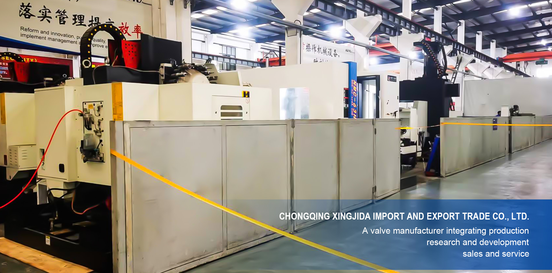
Chongqing Xingjida Import and Export Trading Co., Ltd. is a valve production enterprise that integrates production, research and development, sales, and service. The company has a high-quality modern technology team, which ensures the high quality and stability of the company's products through scientific management, advanced production processes, and perfect testing equipment. The company also provides customers with higher added value fluid control comprehensive solutions by deepening services, taking technology as the leader, and supporting process and production.

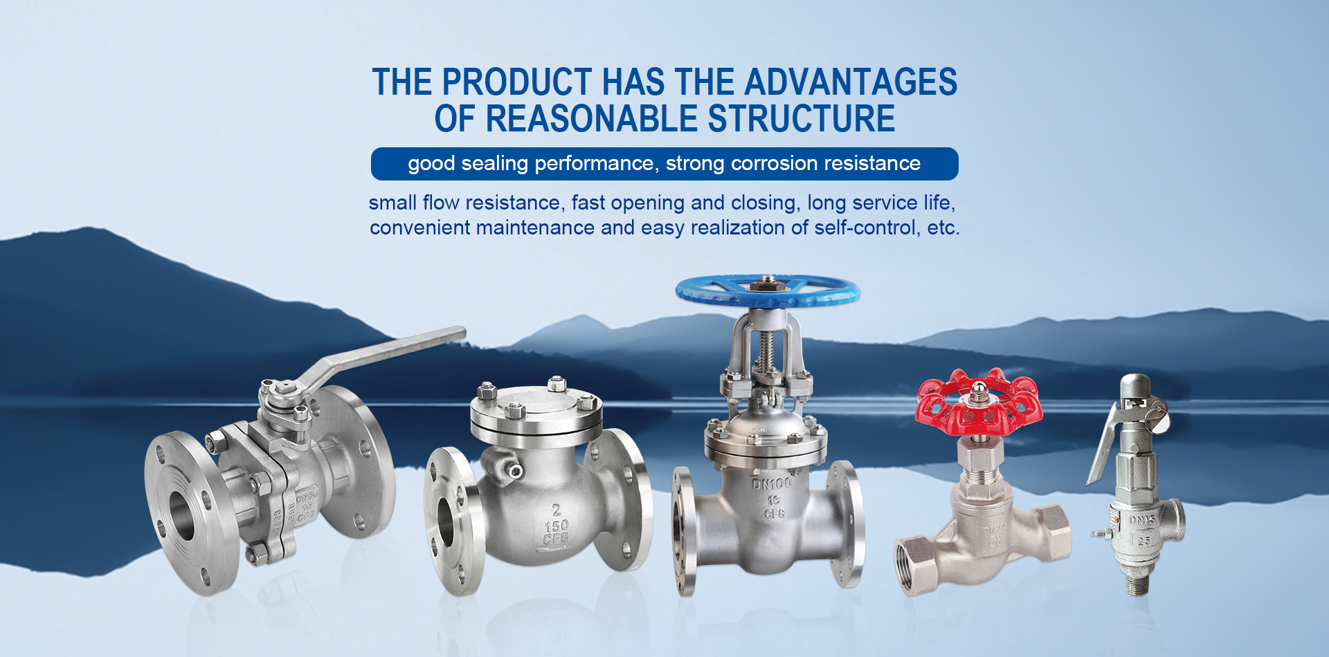
The company's main products include cast steel, stainless steel, and cast iron: butterfly valves, gate valves, globe valves, check valves, ball and knife gate valves, plug valves, safety valves, exhaust valves, relief valves, plunger valves, etc., suitable for industries such as petroleum, chemical, pharmaceutical, coal, metallurgy, municipal, water supply and drainage.

OUR PRODUCTMORE >>
The company has strong technical strength and is engaged in valve production

From raw materials to finished products, they are carefully inspected and tested, and strict quality control is implemented to ensure the reliability and stability of product quality.

The product has the advantages of reasonable structure, good sealing performance, strong corrosion resistance, small flow resistance, fast opening and closing, long service life, convenient maintenance, and easy implementation of self-control.

LATEST NEWS

Application of Pressure Relief Valve in textile production

In textile production, the drying method of sizing machines is to use drying cylinder heating. Its working principle is that the wet sizing yarn is in direct contact with the surface of the high-temperature metal drying cylinder. The surface of the drying cylinder obtains heat and transfers it to the surface of the sizing yarn, so that the moisture contained in the sizing yarn is continuously vaporized, the moisture regain rate of the sizing yarn is continuously reduced, and the surface of the sizing yarn is gradually formed. Serosa. A layer of condensed water formed on the inner surface of the drying cylinder adheres to the inner wall of the drying cylinder. The condensed water accumulated at the lower end of the drying cylinder is discharged through the drain trap. Therefore, the correct selection and daily maintenance of the Pressure Relief Valve are particularly important. In order to ensure that the condensed water in the drying cylinder can be discharged in time, the method of increasing the steam pressure is usually adopted. In this way, a large amount of steam is wasted, and the safe use of the drying cylinder cannot be guaranteed. Therefore, in order to make good use of the drying drum sizing machine and achieve the goals of good sizing quality and low energy consumption, the correct selection of Pressure Relief Valve is crucial, and this is often ignored by sizing machine manufacturers and users. (1) The steam pressure of the drying cylinder cannot be stable and is relatively fluctuating. The steam trap is required to be able to adapt to the changing steam pressure. (2) The speed of the sizing machine also changes. The speed may be fast, slow or stopped. The hydrophobic device must be able to adapt to the hydrophobic amount under different loads. The biggest advantage of the Pressure Relief Valve is that it is not affected by fluctuations in pressure, temperature and condensate flow. It continuously drains water and drains water as soon as it is present. The minimum subcooling degree is 0°C, which can enable the heating equipment to achieve optimal working efficiency; the valve of the Pressure Relief Valve The seat is always below the liquid level, forming a water seal and no steam leakage; its low working pressure is 0.01Mpa, and the maximum back pressure rate is ≤85%; it has an exhaust device inside, and the Pressure Relief Valve uses advanced diaphragm components as automatic The air exhaust valve can automatically eliminate non-condensable gases. It is very sensitive, has high working quality and long service life. Ideal Pressure Relief Valve for heating equipment.

19 April-2024

Pressure Relief Valve installation instructions

1. Control the pressure difference adjustment method: adjust the pressure regulating valve stem counterclockwise and observe the pressure difference; 2. The flow direction of the Pressure Relief Valve medium should be consistent with the direction of the arrow on the valve body; 3. A filter should be installed on the water supply pipe in front of the pressure pipe to prevent the valve from losing its automatic adjustment function due to poor water quality; 4. The water supply pipe of the Pressure Relief Valve valve and the return pipe in front of the valve should be equipped with pressure gauges to facilitate adjustment and control of the pressure difference; 5. If the flow of the Pressure Relief Valve is found to be too large or too small in the system, the possible reason is that debris during the installation of the pipeline components is stuck on the valve plug. The 1/2″ ball valve can be closed for 3-5 minutes. At this time, if If the blockage is minor, it can be eliminated automatically. If it still cannot be eliminated, the valve must be disassembled to check and eliminate the blockage; 6. The Pressure Relief Valve should be installed on the return pipe, with the pressure guiding pipe connected to the valve. The other end of the pressure guiding pipe is connected to the water supply pipe. It is recommended to install a 1/2″ ball valve at the water supply end of the pressure guiding pipe to start the blockage elimination function.

18 April-2024

Solution to Steam Trap pressure problem

The cross-pressure problem of Steam Trap is not a common phenomenon, but it is also a possible failure problem. As users, we still need to have a good understanding of it and master the ability to analyze and solve its causes: Due to the rupture of the pipe network in the pipe section behind the Universal Valve, the valve at P1 is closed or repaired, and when the water pump in pump station A stops running, the water pressure in the pipe section behind the Universal Valve is very low or even empty. When normal water supply is restored, the valve in the pipe section in front of the Universal Valve is suddenly opened or the water pump in pumping station A is turned on, the pressure in the pipe section in front of the Universal Valve increases rapidly, and a large pressure difference exists between the pipe section in front of the Steam Trap and the pipe section behind the Steam Trap in a short period of time. , the Universal Valve has no time to work, and the pressure in the upper chamber of the Universal Valve is very small. Driven by this larger pressure, the Universal Valve is forcibly opened, causing the pressure before and after the Universal Valve to become balanced, and the Universal Valve fails in a short time, that is, a series of pressures. 1. Based on the working principle of the Universal Valve, a pressure relief valve is installed behind the Universal Valve. When the pressure behind the Universal Valve is higher than P2, the pressure relief valve is opened to relieve the pressure and protect the normal water supply pressure of Village A. 2. Use other methods to shorten the series pressure time and make it close to 0. 3. According to the working principle of the Steam Trap, appropriately increase the diameter of the pilot valve and conduit to reduce the time for the upper and lower chambers to reach pressure balance, or even the time difference tending to zero. Through practice verification, the second solution mentioned above is economical and practical. It can be quickly opened through the drain valve, so that the pressure in the upper chamber of the diaphragm is greater than the pressure in the lower chamber, prompting the Steam Trap to quickly return to normal. The series pressure time is basically 0.

17 April-2024

How Steam Trap work

1. When the pneumatic actuator is connected to the circuit and system air source, air enters cylinder A (cylinder B) through pipe A or B to push the piston to move to one end, thereby driving the rotating shaft and ball core to rotate 90°. 2. The top of the pneumatic actuator is linked to the visual indicator. When the green sign points to the word "open", it indicates that the Steam Trap is open. 3. When the green light of the reply signal light is on, the Steam Trap is in the open position, and when the red light is on, the Steam Trap is in the closed position. 4. The positioner can adjust the flow rate of the Steam Trap pipe 5. The valve seat adopts an elastic sealing structure, which ensures reliable sealing and easy opening and closing. 6. The valve stem adopts a bottom-mounted structure with an inverted seal. When the valve cavity is abnormally pressurized, the valve stem will not be impacted. 7. The pneumatic piston actuator is made of low-friction material as the bearing sleeve, and the outer and outer surfaces of the cylinder are treated with hard anodizing for anti-corrosion, which greatly extends the service life of the cylinder.

16 April-2024

Common Steam Trap failures and how to deal with them

The main cause of Steam Trap failure is improper design, manufacturing, selection or use. If these faults are not eliminated in time, they will affect the efficiency and life of the valve, and may even fail to provide safety protection. Common faults and solutions are as follows: (1) Leakage. Under the normal operating pressure of the equipment, leakage exceeding the allowable level occurs between the valve disc and the valve seat sealing surface. The reasons are: there is dirt between the valve disc and the valve seat sealing surface. You can use a lifting wrench to open the valve several times to wash away the dirt and damage the sealing surface. It should be repaired by grinding or turning and then grinding according to the degree of damage; the valve stem is bent or tilted or the lever and fulcrum are deflected, causing the valve core and valve disc to be misaligned. It should be reassembled or replaced; the spring elasticity is reduced or lost. Measures such as replacing the spring and readjusting the opening pressure should be taken. (2) It will not open when the specified pressure is reached. The reason for this situation is inaccurate pressure setting. The compression amount of the spring or the position of the weight should be readjusted; the valve disc and valve seat are stuck. The Steam Trap should be manually deflated or drained regularly; the lever of the lever Steam Trap is stuck or the weight is moved. The weight should be repositioned so that the lever can move freely. (3) Opening when the pressure is less than the specified pressure. The main reason is that the constant pressure is inaccurate; the elasticity of the spring decreases due to aging. The adjusting screw should be tightened appropriately or the spring should be replaced. (4) The pressure continues to rise after exhausting. This is mainly because the selected Steam Trap has a smaller displacement than the safe discharge capacity of the equipment. A suitable Steam Trap should be re-selected; the center line of the valve stem is incorrect or the spring is rusty, so that the valve disc cannot open to the height it should be and should be reassembled. Valve stem or replace the spring; the exhaust pipe is not cut enough, an exhaust pipe that meets the safe discharge area should be used. (5) The valve disc does not return to its seat after discharge. This is mainly caused by the spring bending the valve stem, the valve disc being installed in an incorrect position or being stuck. Should be reassembled. (6) The valve flap jumps or vibrates frequently. Mainly due to the spring stiffness being too high. A spring with appropriate stiffness should be used instead; the adjustment ring is improperly adjusted, causing the return pressure to be too high. The position of the adjusting ring should be readjusted; the resistance of the discharge pipe is too large, causing large discharge back pressure. Discharge pipe resistance should be reduced.

15 April-2024

We will contact you immediately

Fill in more information so that we can get in touch with you faster

Privacy statement: Your privacy is very important to Us. Our company promises not to disclose your personal information to any external company with out your explicit permission.

Send